Archive - TaskCam 3D-printed Version 1
Various components of the TaskCam Version 1.0 are not manufactured anymore. Go to TaskCam Version 2.0 to build the current TaskCam.
Specifications:
TaskCam Version 1.0
Camera Dimensions 120 x 50 x 109mm
Image resolution 640 x 480 pixel
TaskCam V1 beta software
TaskCam shield version 1
TaskCams recreate the proven Cultural Probe technique of relabelling disposable cameras with requests for pictures. The 3D Printed TaskCam is the basic workhorse of the collection, robust and flexible enough to use across multiple studies.
The 3D Printed TaskCam has a small screen on the back that shows a scrollable list of requests for pictures. Researchers can load their own list of requests onto the camera to prepare for a study. When users take a picture, the image is tagged with the current request, and stored on a standard flash drive that can be removed for downloading.
The casing for the 3D Printed TaskCam can be printed successfully without support materials even on low-end printers. The device requires a custom PCB, based on the Arduino platform, that you can make yourself or buy online. Two AA batteries provide enough power for days or weeks of occasional use.
List of all the components to assemble the TaskCam
TaskCam shield version 1
Arduino Uno or compatible
Linksprite JPG Camera
3D printed case
Micro SD card
AA battery holder
2 x AA batteries
2 x No.2 6.4mm and 2 x No.2 9.5mm self-tapping screws available here
2 x 2mm cable tie
List of handy equipment
small Phillips screw driver (cross top)
3D printer

Step 1 Print camera case and slide switch

Step 2 Connect camera module to shield. Make sure to match the order of the cables with the picture. Top to bottom: red, brown, purple, grey. Solder battery leads to the board observing the correct polarity.

Step 3 Plug shield into Arduino. Take care to align the pins with the Arduino’s sockets. Your shield is now ready to use.

Step 4 Your camera needs some questions. For advice on how to write good Probe questions, please read here. Insert the micro SD card into your computer. Write your questions in the text box below, giving each question a new line. Once you're done, click "Download questions file". Your browser will download a file called "q.txt". Place that file into the SD card. Eject it and unplug it from your computer.

Step 5 Upload code to Arduino
Install Arduino on your computer in order to upload the camera program to your Arduino board. Follow Arduino’s guide here. Note that Arduino has a new Web Editor. Please download the Desktop IDE instead.
Once you've installed the Arduino IDE, open it. We now need to download some extra libraries that the TaskCam uses. They’re available from the Library Manager.
Go to Sketch > Include Library > Manage Libraries…
After the Library Manager loads and updates, search for “Adafruit GFX”. The first result will be the Adafruit GFX Library. Go ahead and click on it. Click install.
Now search for “Adafruit SSD1306”. The first result is the Adafruit SSD1306 library. Go ahead and click on it. Click install. You should now have everything you need in your Arduino setup.
Download the code from here. Open the ProbeCam_Arduino.ino file in the folder. This should open the code in the Arduino environment.
We need to make sure that the Arduino program can talk to the board. Plug your Arduino board into your computer with the USB cable.
Go to Tools > Board > Arduino / Genuino Uno. This is the type of board that the camera uses.
We also need to select the right USB port through which we’ll upload the program. Go to Tools > Port. If you’re on Windows, you should be able to see a COM port. If you’re on Mac or Linux, you should be able to see a couple of ports, and one should say Arduino next to it. Go ahead and click on the right port. If you can’t find your Arduino in this menu, refer to Arduino's troubleshooting page.
You’re ready to upload the code to your board! Press the Upload button on the top of your code window (the button next to the tick). After a few seconds, you should see the message “Done uploading.”

Step 6 Plug the micro SD card into the shield. Unplug the Arduino’s USB cable and plug it back in. Once the camera starts up, you should be able to see your questions scroll across the screen.

Step 7 Plug the two AA batteries into the battery holder

Step 8 Make sure you give the camera a thorough test before it goes into its housing by running through its main functions. Scroll between questions, take a picture, and turn it off and on again with the switch. Once you’re happy that everything works, you’re ready to put the electronics into their housing.
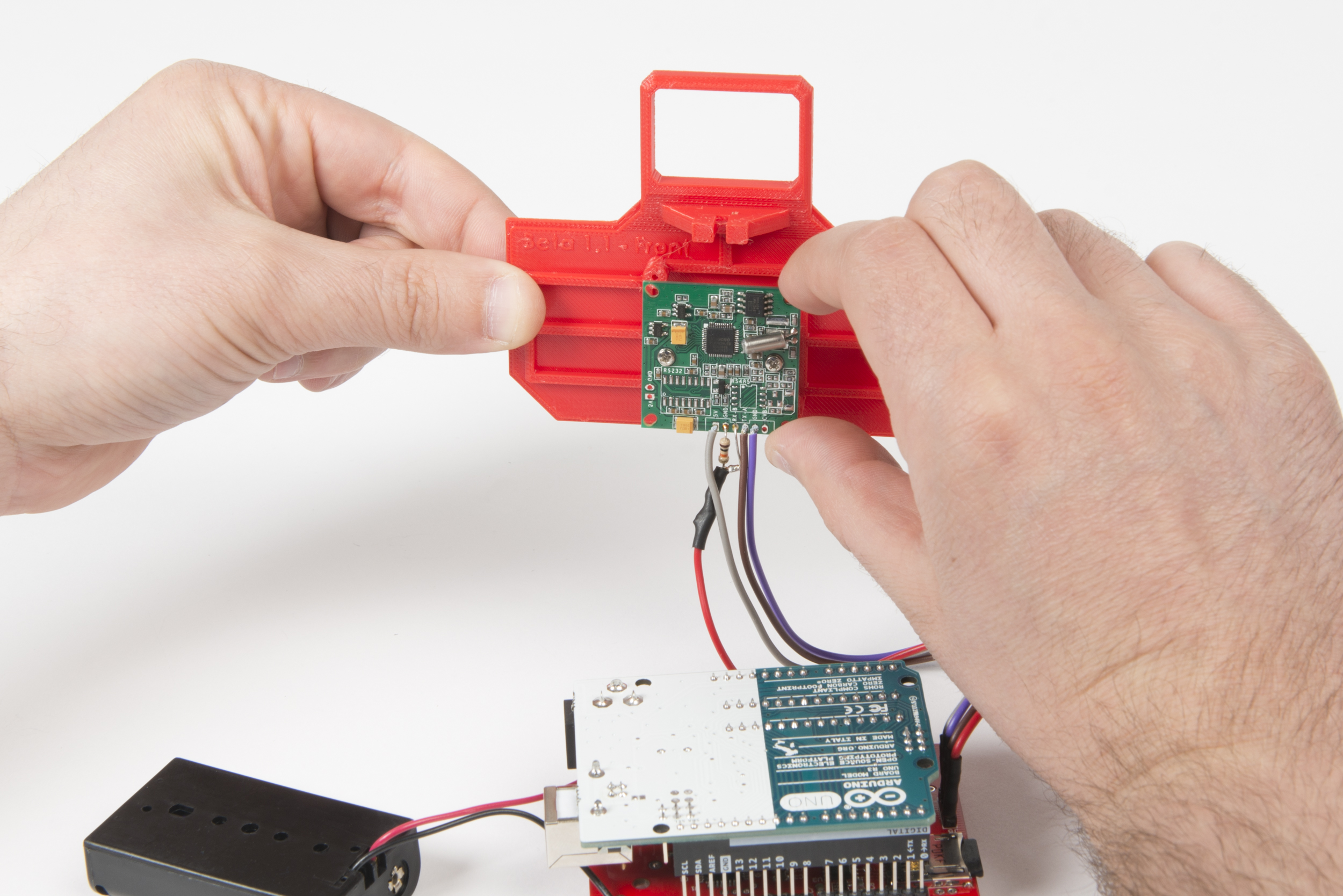
Step 9 Plug the camera into the front panel.

Step 10 Secure the camera to the front panel with the two screws.

Step 11 Slot the front panel into its matching channel on the main housing.

Step 12 Insert the battery holder into its position.

Step 13 Place the switch into its slot in the top lid.
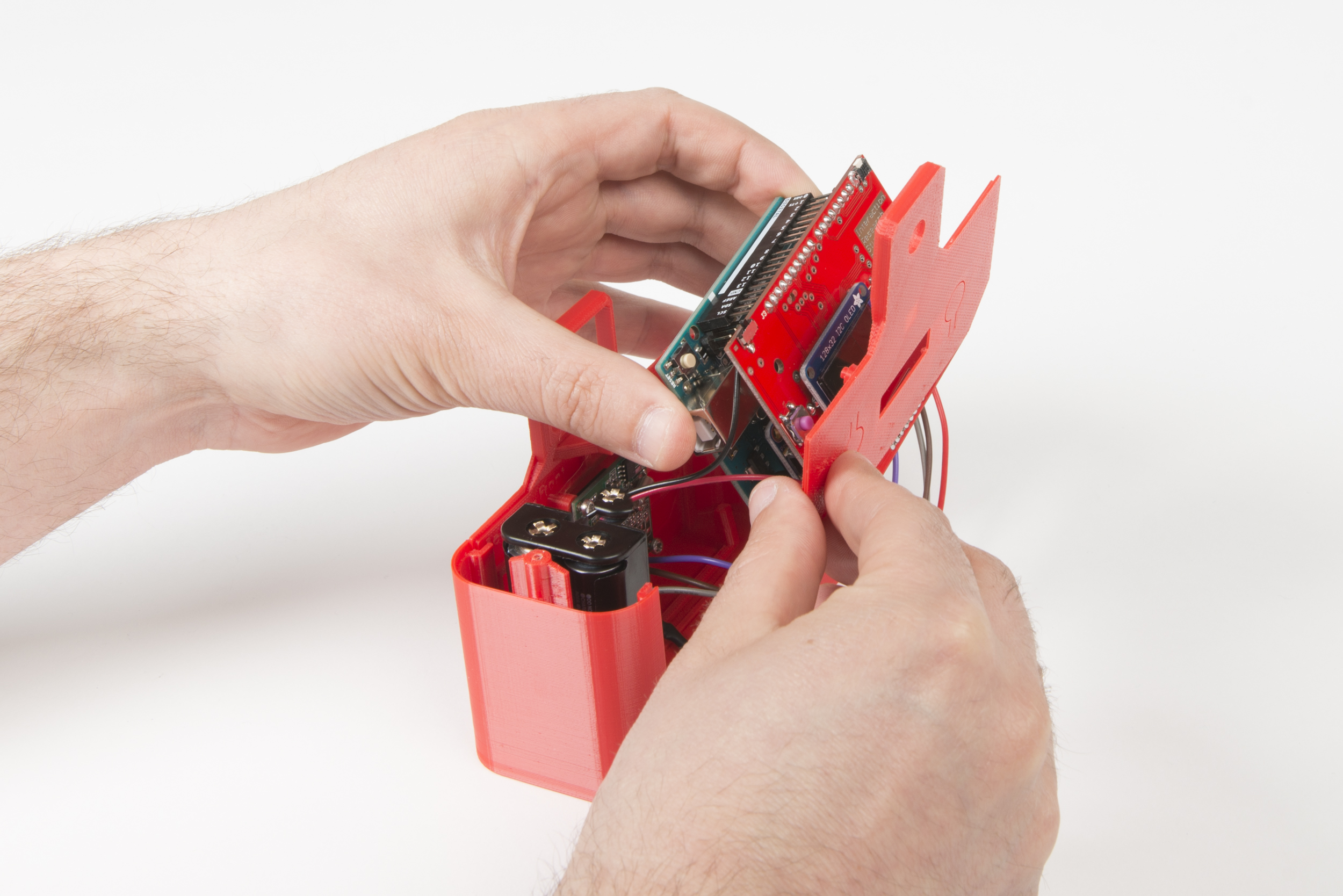
Step 14 Match the locating pins on the back panel with the holes on the TaskCam shield.

Step 15 Whilst holding the top lid upside down, carefully insert the back panel with the shield into the top lid.

Step 16 Finally, insert the whole assembly into the matching channel in the main case.

Step 17 Secure the camera case by inserting two screws on the top lid.

Step 18 Your TaskCam is now complete!
How to use


Turn camera on swiping the power button to the left. A red light flashes on backside and the display turns on
Select a task with the left and right button next to the display
Use the viewfinder to frame your picture, press the shutter button to take a picture that answers the task. The display graphic changes when a picture is taken
Select your next task
Turn off after use